take a few minutes to answer the survey.
Click here to take survey
Friday, 30 July 2010
Pressure valves
The function of pressure valves, is to influence the pressure in an overall pneumatic system or in a part of the system. Pressure regulating valves are generally adjustable against spring compression. The symbols are distinguished according to the following types:
- Pressure regulating valve without relief port
- Pressure regulating valve with relief port
- Pressure sequence valves

The symbols represent the pressure valve as a single position valve with a flow path that is either open or closed initially. In the case of the pressure regulator the flow is always open, whereas the pressure sequence valve is closed until the pressure reaches the limit value as set on the adjustable spring.
Flow control valves
Most flow control valves are adjustable and permit flow control in both directions. The arrow shows that the component is adjustable but does not refer to the direction of flow; it is diagrammatic only.
In the case of the one-way flow control valve, a non-return valve is switched in parallel with the flow control valve. Flow control is effected in one direction only.

In the case of the one-way flow control valve, a non-return valve is switched in parallel with the flow control valve. Flow control is effected in one direction only.

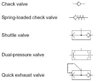
Non-return valves & Derivatives
The non-return valve (check valve) is the basis for the development of many combined components. There are two main configurations for nonreturn valves, with and without the spring return. In order to release flow, the pressure force on the spring return design must be greater than the spring force.


Methods of actuation
The methods of actuation of pneumatic directional control valves is dependent upon the requirements of the task. The types of actuation vary, e.g.
- manually actuated
- mechanically actuated
- pneumatically actuated
- electrical and
- combined actuation.
The symbols for the methods of actuation are detailed in DIN ISO 1219.
When applied to a directional control valve, consideration must be given to the method of initial actuation of the valve and also the method of return actuation. Normally these are two separate methods. They are both shown on the symbol either side of the position boxes. There may also be additional methods of actuation such as manual overrides, which are separately indicated.
Directional Control Valves
The directional control valve is represented by the number of controlled connections, the number of positions and the flow path. In order to avoid faulty connections, all the inputs and outputs of a valve are identified.

A numbering system is used to designate directional control valves and is in accordance with DIN ISO 5599-3. Prior to this a lettering system was utilised and both systems of designation are presented here:
working lines

Pilot lines


A numbering system is used to designate directional control valves and is in accordance with DIN ISO 5599-3. Prior to this a lettering system was utilised and both systems of designation are presented here:
working lines

Pilot lines


Symbols and descriptions of components
The development of pneumatic systems is assisted by a uniform approach to the representation of the elements and the circuits. The symbols used for the individual elements must display the following characteristics:
- Actuation and return actuation methods
- Number of connections (all labelled for identification)
- Number of switching positions
- General operating principle
- Simplified representation of the flow path
The technical construction of the component is not taken into account in the abstract symbol form.
The symbols used in pneumatics are detailed in the standard DIN ISO 1219, "Circuit symbols for fluidic equipment and systems".
Subscribe to:
Posts (Atom)
